


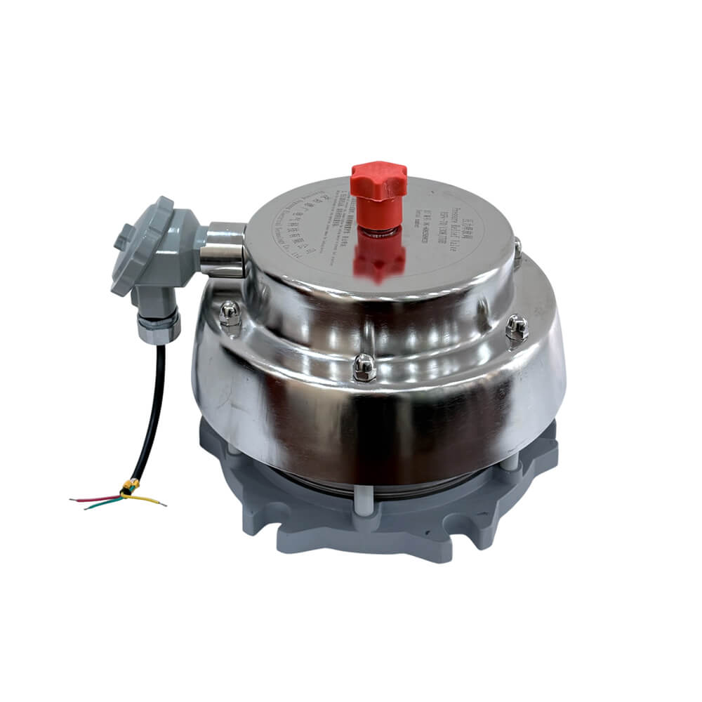

YSF9-80K、130K Series Pressure Relief Device
Pressure relief device with diameters of Φ 80mm and Φ 130mm are mainly suitable for releasing pressure inside oil tanks of large oil immersed power transformers, power capacitors, reactors, and other equipment when the pressure exceeds the limit. In addition to the conventional electrical alarm signal, a computer electrical alarm signal function can also be added to achieve dual electrical signal output, and each can be independently led out. Users can choose according to their needs when ordering products.


1. Installation position: on the oil tank cap, on the raised seat, or on the upper side wall of the oil tank.
2. Environmental requirements: -30 ℃ to+70 ℃(can be customized according to user needs to support up to -45 ℃ to+70 ℃); Work environment requirements:- 30℃~+115℃(customizable according to user needs, can support up to -45 ℃~+115 ℃).
3. Relative humidity: not exceeding 95% at+20 ℃.
4. Protection level: IP55(Customizable according to user requirements). Scope of application: Altitude 0~4000m.
5. Power frequency withstand voltage: normally open contact 2000V/min, normally closed contact or single pole double throw contact: phase to phase 1000V/min, ground 2000V/min.
6. Insulation performance: normally open contact 2500V, 1000M Ω, normally closed contact or single pole double throw contact: phase to phase 1000V, 500M Ω, ground 2500V, 1000M Ω.
The oil injection diameter is Ø 80 and Ø 130 with electrical signal but without directional injection. The pressure relief device is connected by bolts as shown in the following figure and table.
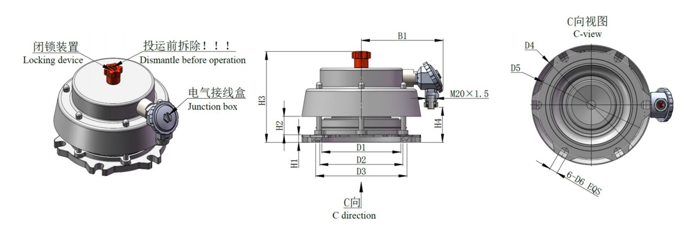
Outline drawing of YSF9 type without directional injection pressure relief device
| Specifications | D1 | D2 | D3 | D4 | D5 | D6 | H1 | H2 | H3 | H4 | B1 |
| YSF9-XX/80 (S)KJTHB |
122 | 132 | 151 | 200 | 170 | 14 | 16 | 40 | 200 | 70 | 162 |
| YSF9-XX/130 (S)KJTHB |
172 | 188 | 208 | 260 | 235 | 18 | 17 | 55 | 215 | 85 | 180 |
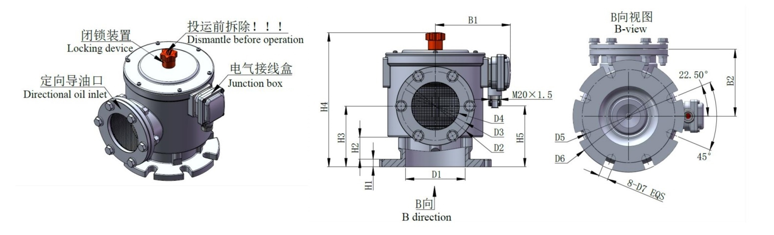
The oil injection diameter is Ø 80 and Ø 130, with electrical signals and directional injection. The pressure relief device is connected by bolts as shown in the following figure and table.
Outline drawing of YSF9 directional injection pressure relief device
| Specifications | D1 | D2 | D3 | D4 | D5 | D6 | D7 | D8 | H1 | H2 | H3 | H4 | H5 | B1 | B2 |
| YSF9-XX/80 (S)KJTHB |
122 | 132 | 151 | 144 | 100 | 170 | 200 | 14 | 15 | 33 | 113 | 265 | 105 | 162 | 140 |
| YSF9-XX/130 (S)KJTHB |
180 | 188 | 208 | 200 | 148 | 235 | 260 | 18 | 16 | 33 | 131 | 288 | 120 | 180 | 175 |
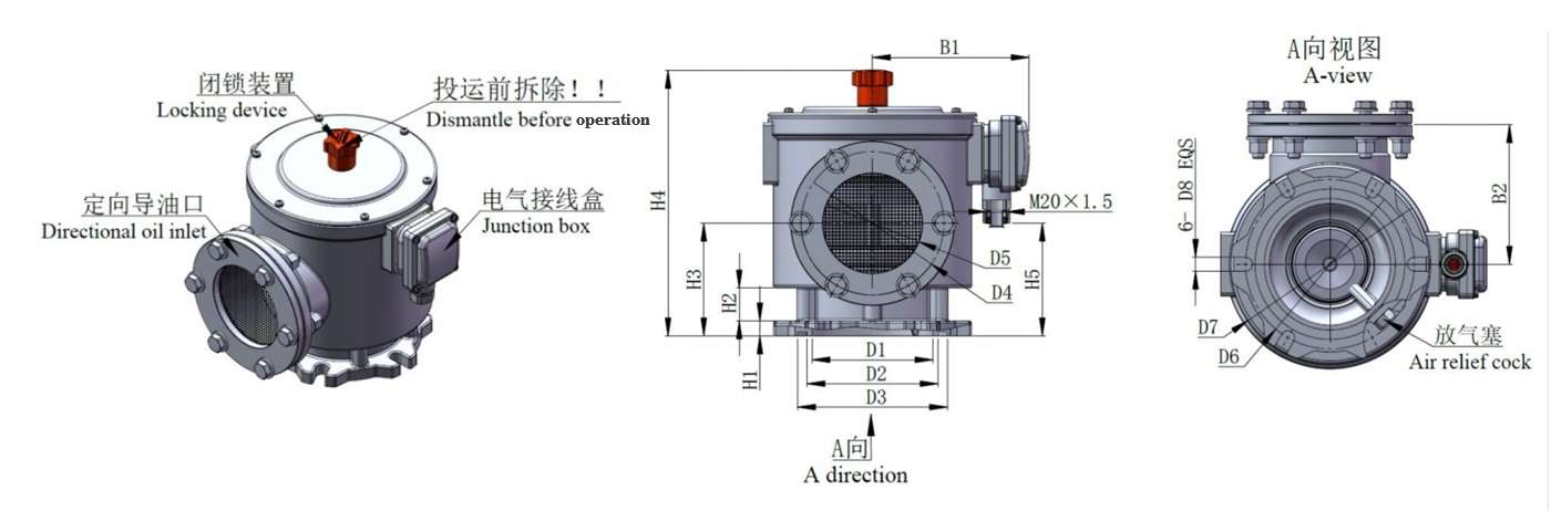
The oil injection diameter is Ø 80 and Ø 130, with electrical signals and directional injection. The pressure relief device (8-hole) is connected by bolts as shown in the following figure and table.
Outline drawing of YSF10 directional injection pressure relief device
| Specifications | D1 | D2 | D3 | D4 | D5 | D6 | D7 | H1 | H2 | H3 | H4 | H5 | B1 | B2 |
| YSF9-XX/80 (S)KJTHB |
126 | 165 | 144 | 100 | 195 | 235 | 20 | 16 | 45 | 125 | 285 | 120 | 160 | 140 |
| YSF9-XX/130 (S)KJTHB |
166 | 225 | 200 | 148 | 240 | 280 | 24 | 17 | 45 | 145 | 307 | 130 | 186 | 175 |

Torque Reference Table
| Number | Assembly position | Thread specification | Recommended torque | Assembly tool specifications | Notes | ||
| 1 | Connecting terminal | M3 | 0.5~1Nm |  |
PH2 | Suggest manual installation |
|
| 2 | Terminal box cover | M4 | 1.5~2Nm | |
PH2 | Suggest manual installation |
|
| 3 | Flange installation hole |
YSF9-80 | M12 bolt | 35~40Nm |  |
19mm | |
| YSF9-130 | M16 bolt | 65~75Nm | |
24mm | |||
| YSF10-80 | M16 bolt | 65~75Nm | |
24mm | |||
| YSF10-130 | M20 bolt | 120~135 Nm | |
30mm | |||
| 4 | Directional oil inlet | M10 | 18~22Nm | |
17mm | ||
The product provides a variety of color options, specifically described as follows:
| Color card No | Color | Optionality of choice |
| RAL7038 | Agate grey | Default |
| RAL7042 | A Traffic grey A | Optional |
| RAL7035 | Light grey | Optional |


Contact Us
 Tel: 024-23825580
 Email: info@cndeguang.com
 WHATSAPP: +86 15040033053
 Add: Xiangrui Industrial Park, Hunnan New District, Shenyang City, Liaoning Province, China


Integrate closely with upstream R&D, deeply optimize downstream strategic cooperation,continuously lead the domestic market, and pursue innovative development and overseas expansion.
sitemaps


 +86 15040033053
 15040033053/13072495515
 info@cndeguang.com
