

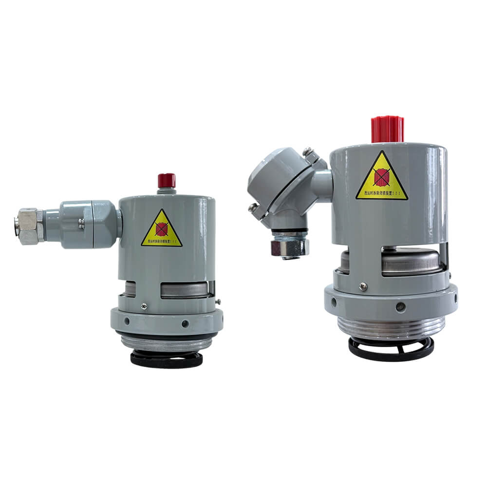


YSF9-25K、50K Series Pressure Relief Device
The YSF series pressure relief device with a diameter of less than 50mm is a new type of pressure relief device. This product is used to protect oil tanks of oil immersed electrical equipment, such as transformers, high-voltage switches, power capacitors, reactors, on load tap changers, etc.


1. Installation position: on the oil tank cap, on the raised seat, or on the upper side wall of the oil tank.
2. Environmental requirements: -30 ℃ to+70 ℃(can be customized according to user needs to support up to -45 ℃ to+70 ℃); Work environment requirements:-30℃~+115℃(customizable according to user needs, can support up to -45 ℃~+115 ℃).
3. Relative humidity: not exceeding 95% at+20 ℃.
4. Protection level: IP55(Customizable according to user requirements). Scope of application: Altitude 0~4000m.
5. Power frequency withstand voltage: normally open contact: 2000V/min, normally closed contact: 1000V/min, ground 2000V/min.
6. Normally open contact: 2500V, 1000M Ω, normally closed contact: 1000V, 500M Ω, ground 2500V, 1000M Ω.
1. Pressure relief device with diameters of 25 and 50 (threaded connection, with mechanical alarm type) as shown in the following figure and table.
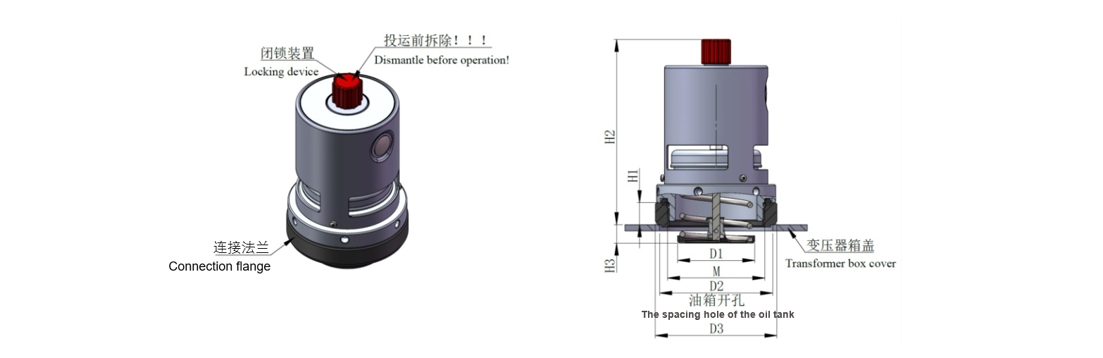
| Product model | Caliber | D1 | D2 | D3 | H1 | H2 | H3 | M |
| YSF9(/6)-XX/25JTHB | Φ25 | Φ17.5 | Φ55/(Φ40) | Φ60 | 15 | 128 | 11 | M38×2 |
| YSF9(/6)-XX/25JTHB | Φ25 | Φ17.5 | Φ55 | Φ62 | 16 | 136 | 11 | M48×3 |
| YSF9(/6)-XX/50JTHB | Φ50 | Φ64 | Φ93/(Φ70) | Φ100 | 18/(33) | 155/(170) | 13/(-9) | M80×3 |
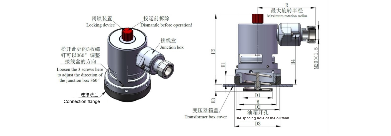
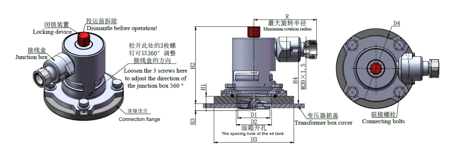
2. Pressure relief device with diameters of 25K and 50K (threaded connection, electrical signal, vertical output, mechanical alarm) as shown in the following figure and table.
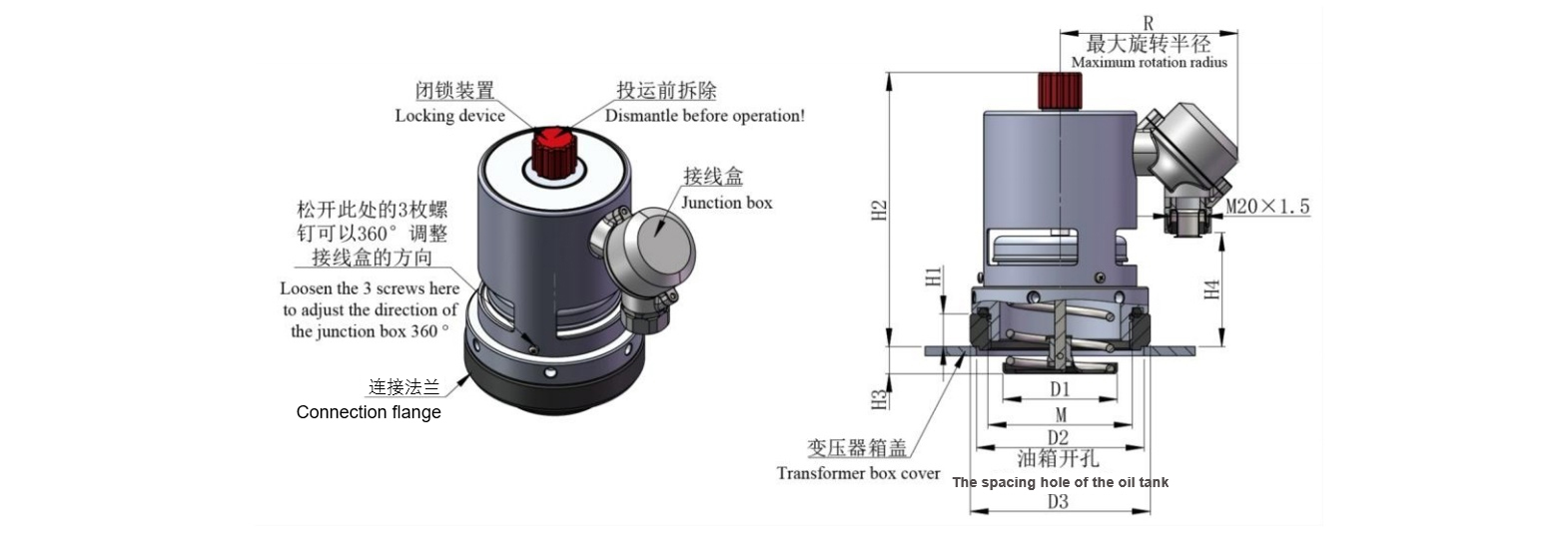
| Product model | Caliber | D1 | D2 | D3 | H1 | H2 | H3 | H4 | R | M |
| YSF9(/6)-XX/25(S)KJTHB | Φ25 | Φ17.5 | Φ55/(Φ40) | Φ60 | 15 | 128 | 11 | 30 | 85 | M38×2 |
| YSF9(/6)-XX/25(S)KJTHB | Φ25 | Φ17.5 | Φ55 | Φ62 | 16 | 138 | 11 | 38 | 85 | M48×3 |
| YSF9(/6)-XX/50(S)KJTHB | Φ50 | Φ64 | Φ93/(Φ70) | Φ100 | 18/(33) | 155/(170) | 13/(-9) | 50(65) | 100 | M80×3 |
3. Pressure relief device with diameters of 25K and 50K (threaded connection, electrical signal, PG waterproof joint, mechanical alarm) as shown in the following figure and table.
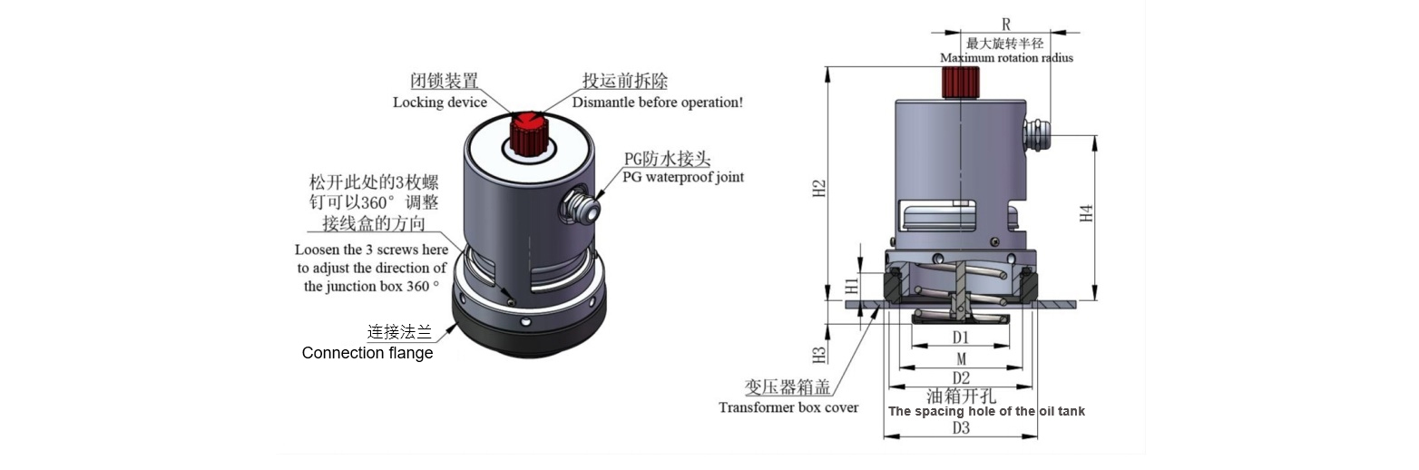
| Product model | Caliber | D1 | D2 | D3 | H1 | H2 | H3 | H4 | R | M |
| YSF9(/6)-XX/25(S)KJTHB | Φ25 | Φ17.5 | Φ55/(Φ40) | Φ60 | 15 | 128 | 11 | 86 | 48 | M38×2 |
| YSF9(/6)-XX/25(S)KJTHB | Φ25 | Φ17.5 | Φ55 | Φ62 | 16 | 138 | 11 | 94 | 48 | M48×3 |
| YSF9(/6)-XX/50(S)KJTHB | Φ50 | Φ64 | Φ93/(Φ70) | Φ100 | 18/(33) | 155/(170) | 13/(-9) | 107(122) | 60 | M80×3 |
4. Pressure relief device with diameters of 25K and 50K (threaded connection, electrical signal, horizontal output, mechanical alarm) as shown in the following figure and table.
| Product model | Caliber | D1 | D2 | D3 | H1 | H2 | H3 | H4 | R | M |
| YSF9(/6)-XX/25(S)KJTHB | Φ25 | Φ17.5 | Φ55/(Φ40) | Φ60 | 15 | 128 | 11 | 86 | 117 | M38×2 |
| YSF9(/6)-XX/25(S)KJTHB | Φ25 | Φ17.5 | Φ55 | Φ62 | 16 | 138 | 11 | 94 | 117 | M48×3 |
| YSF9(/6)-XX/50(S)KJTHB | Φ50 | Φ64 | Φ93/(Φ70) | Φ100 | 18/(33) | 155/(170) | 13/(-9) | 107(122) | 132 | M80×3 |
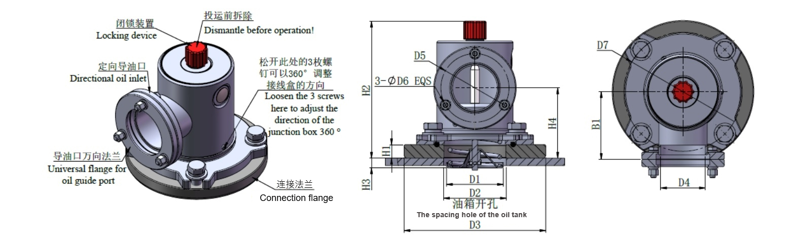
5. Pressure relief device (threaded connection, with directional injection, with mechanical alarm type) with dimensions of 25D and 50D as shown in the following figure and table.
| Product model | Caliber | D1 | D2 | D3 | D4 | D5 | D6 | B1 | H1 | H2 | H3 | H4 | M | Number of directional bolts ×specification |
| YSF9-XX/ 25DJTHB |
Φ25 | Φ17.5 | Φ55/(Φ40) | Φ60 | Φ32 | Φ55 | Φ8 | 57 | 15 | 128 | 11 | 55 | M38×2 | 3×M6-30 |
| YSF9-XX/ 25DJTHB |
Φ25 | Φ17.5 | Φ55 | Φ62 | Φ32 | Φ55 | Φ8 | 57 | 16 | 138 | 11 | 63 | M48×3 | 3×M6-30 |
| YSF9-XX/ 50DJTHB |
Φ50 | Φ64 | Φ93/(Φ70) | Φ100 | Φ50 | Φ75 | Φ8 | 75 | 18/(33) | 155/(170) | 13/(-9) | 79/(94) | M80×3 | 3×M6-35 |
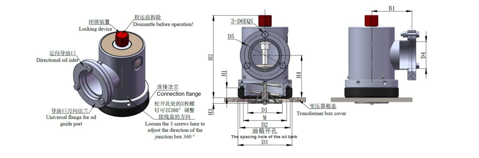
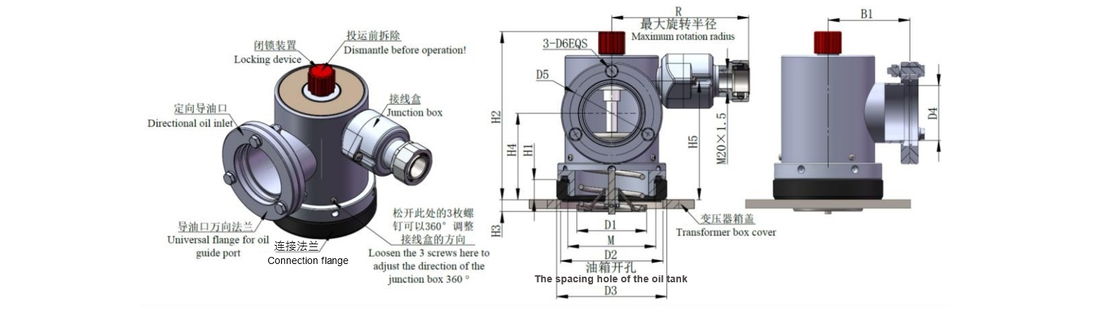
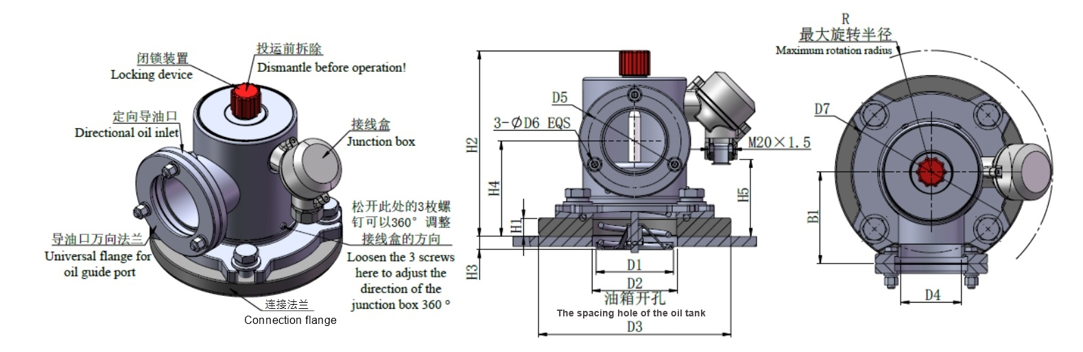
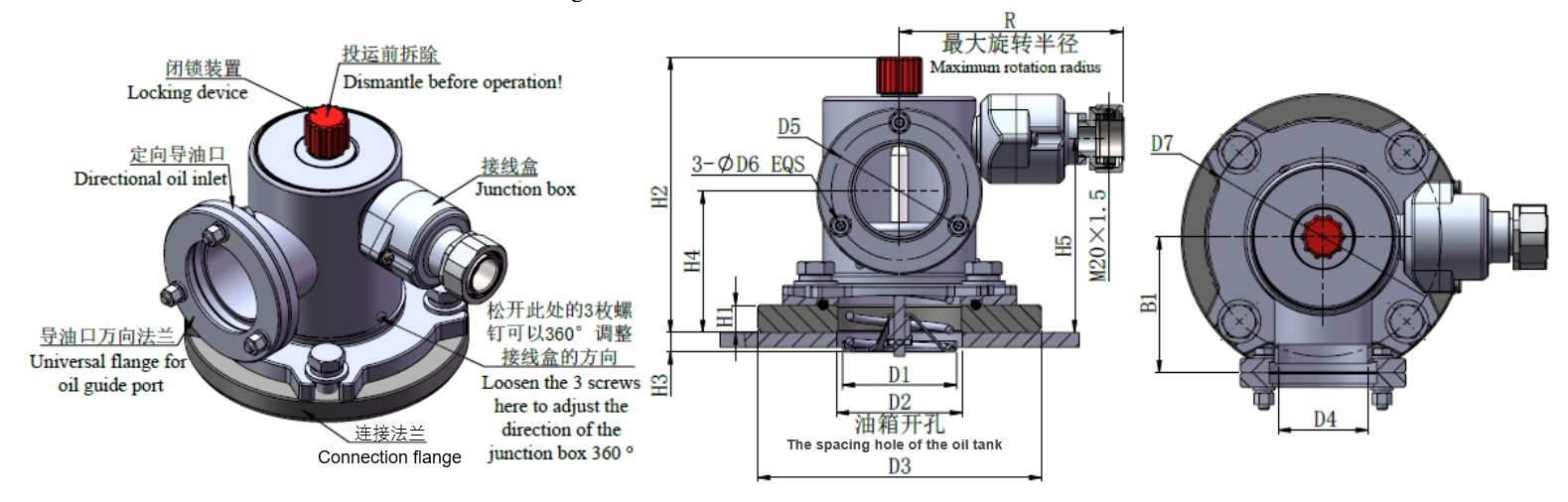
6. Pressure relief device with diameters of 25D and 50D (threaded connection, with directional fuel injection, electrical signal, vertical output, and mechanical alarm) as shown in the following figure and table.
| Product model | Caliber | D1 | D2 | D3 | D4 | D5 | D6 | B1 | H1 | H2 | H3 | H4 | H5 | M | Number of directional bolts ×specification |
| YSF9-XX/ 25D(S)KJTHB |
Φ25 | Φ17.5 | Φ55/(Φ40) | Φ60 | Φ32 | Φ55 | Φ8 | 57 | 15 | 128 | 11 | 55 | 30 | M38×2 | 3×M6-30 |
| YSF9-XX/ 25D(S)KJTHB |
Φ25 | Φ17.5 | Φ55 | Φ62 | Φ32 | Φ55 | Φ8 | 57 | 16 | 138 | 11 | 63 | 38 | M48×3 | 3×M6-30 |
| YSF9-XX/ 50D(S)KJTHB |
Φ50 | Φ64 | Φ93/(Φ70) | Φ100 | Φ50 | Φ75 | Φ8 | 75 | 18/(33) | 155/(170) | 13/(-9) | 79/(94) | 50/65 | M80×3 | 3×M6-35 |
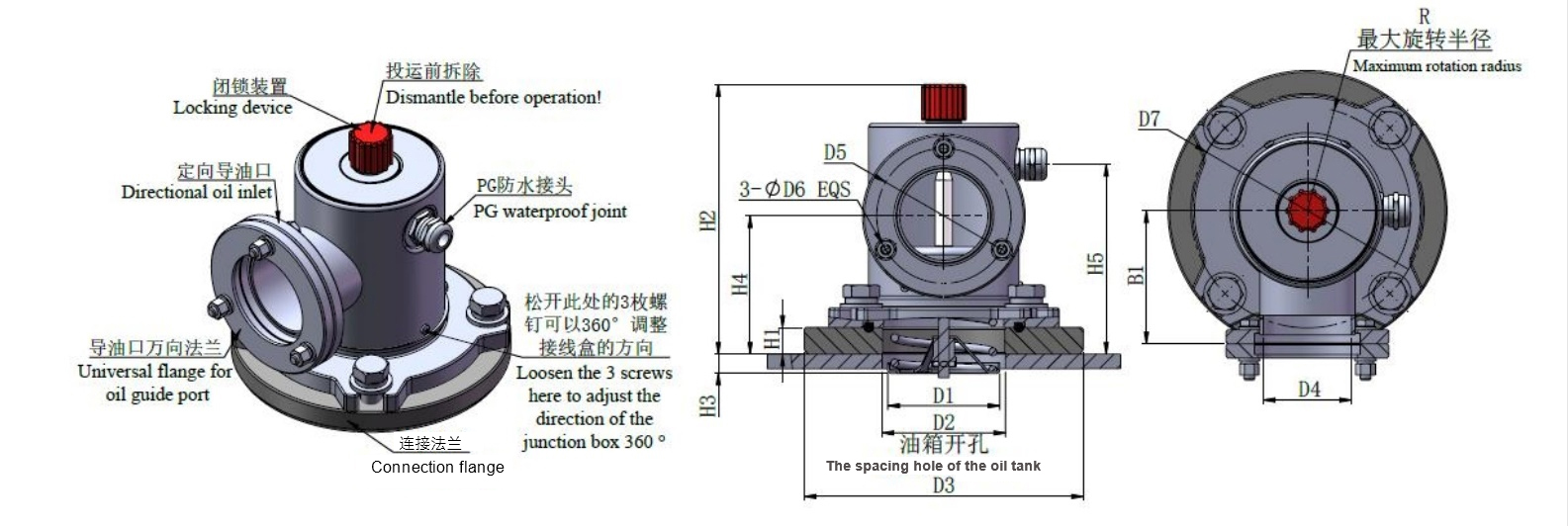
7. Pressure relief device with diameters of 25D and 50D (threaded connection, directional fuel injection, electrical signal, PG waterproof joint, mechanical alarm) as shown in the following figure and table.
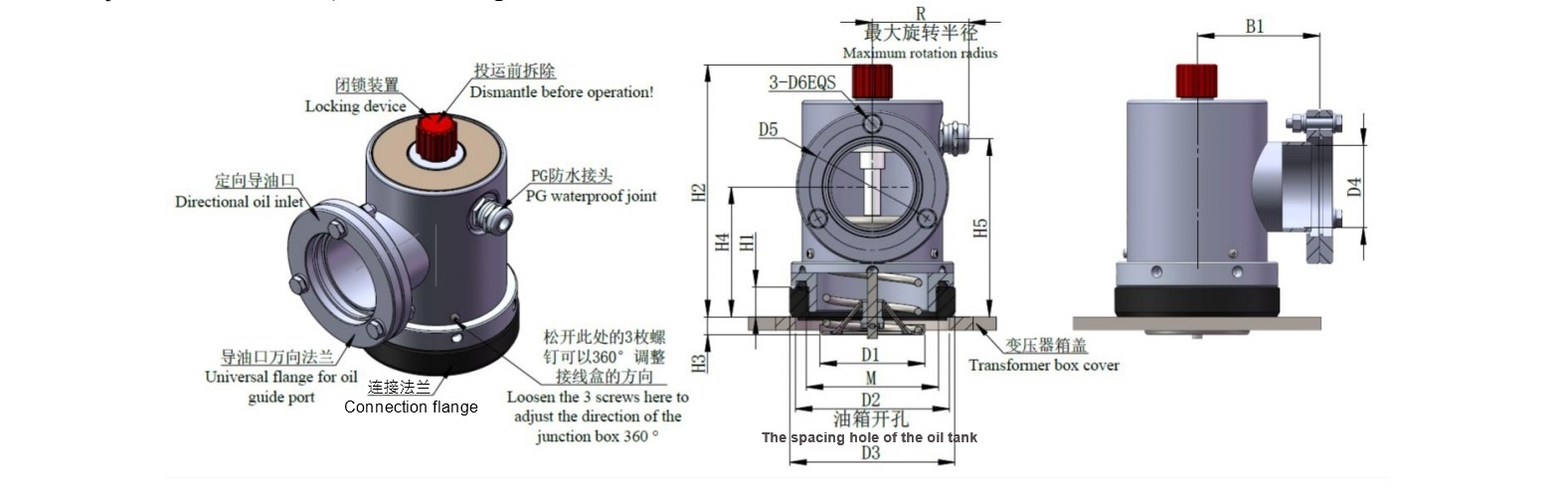
| Product model | Caliber | D1 | D2 | D3 | D4 | D5 | D6 | B1 | R | H1 | H2 | H3 | H4 | H5 | M | Number of directional bolts ×specification |
| YSF9-XX/ 25D(S)KJTHB |
Φ25 | Φ17.5 | Φ55/(Φ40) | Φ60 | Φ32 | Φ55 | Φ8 | 57 | 48 | 15 | 128 | 11 | 55 | 86 | M38×2 | 3×M6-30 |
| YSF9-XX/ 25D(S)KJTHB |
Φ25 | Φ17.5 | Φ55 | Φ62 | Φ32 | Φ55 | Φ8 | 57 | 48 | 16 | 138 | 11 | 63 | 94 | M48×3 | 3×M6-30 |
| YSF9-XX/ 50D(S)KJTHB |
Φ50 | Φ64 | Φ93/(Φ70) | Φ100 | Φ50 | Φ75 | Φ8 | 75 | 60 | 18/(33) | 155/(170) | 13/(-9) | 79/(94) | 107/(122) | M80×3 | 3×M6-35 |
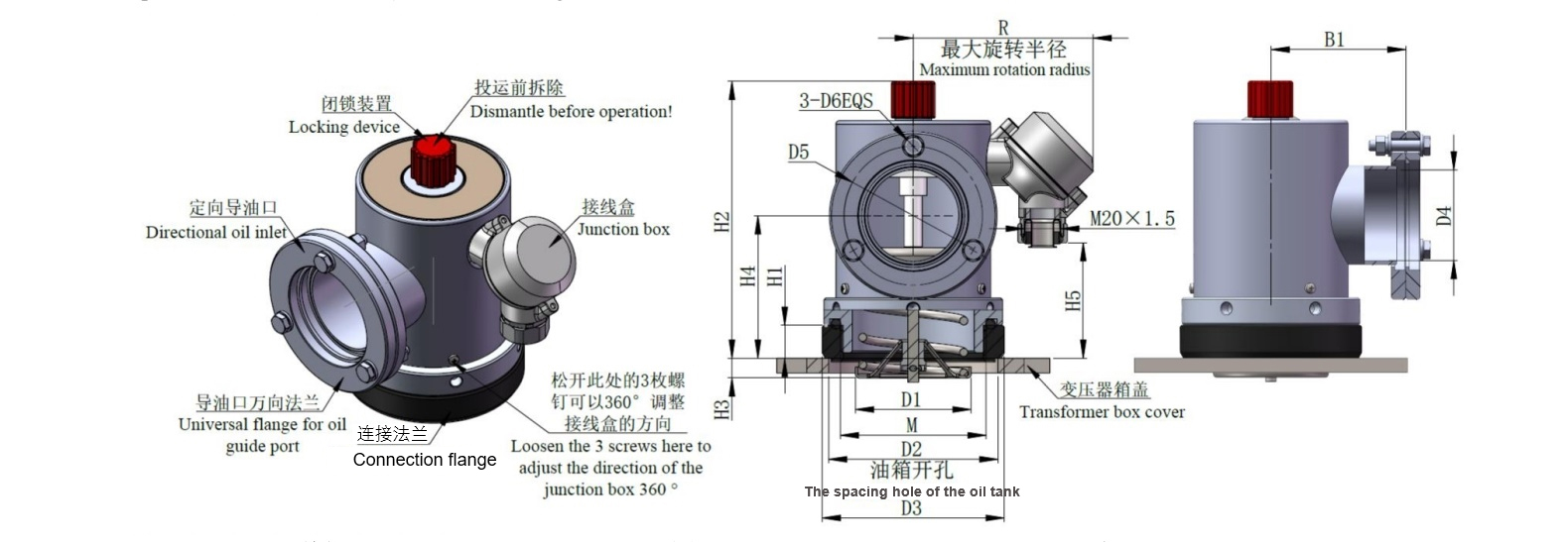
8. Pressure relief device with diameters of 25D and 50D (threaded connection, directional injection, electrical signal, horizontal output, mechanical alarm) as shown in the following figure and table.
| Product model | Caliber | D1 | D2 | D3 | D4 | D5 | D6 | B1 | R | H1 | H2 | H3 | H4 | H5 | M | Number of directional bolts ×specification |
| YSF9-XX/ 25D(S)KJTHB |
Φ25 | Φ17.5 | Φ55/(Φ40) | Φ60 | Φ32 | Φ55 | Φ8 | 57 | 117 | 15 | 128 | 11 | 55 | 86 | M38×2 | 3×M6-30 |
| YSF9-XX/ 25D(S)KJTHB |
Φ25 | Φ17.5 | Φ55 | Φ62 | Φ32 | Φ55 | Φ8 | 57 | 117 | 16 | 138 | 11 | 63 | 94 | M48×3 | 3×M6-30 |
| YSF9-XX/ 50D(S)KJTHB |
Φ50 | Φ64 | Φ93/(Φ70) | Φ100 | Φ50 | Φ75 | Φ8 | 75 | 132 | 18/(33) | 155/(170) | 13/(-9) | 79/(94) | 107/(122) | M80×3 | 3×M6-35 |
9. Pressure relief device (bolted connection, with mechanical alarm type) with a diameter of 25 and 50 as shown in the following figure and table.
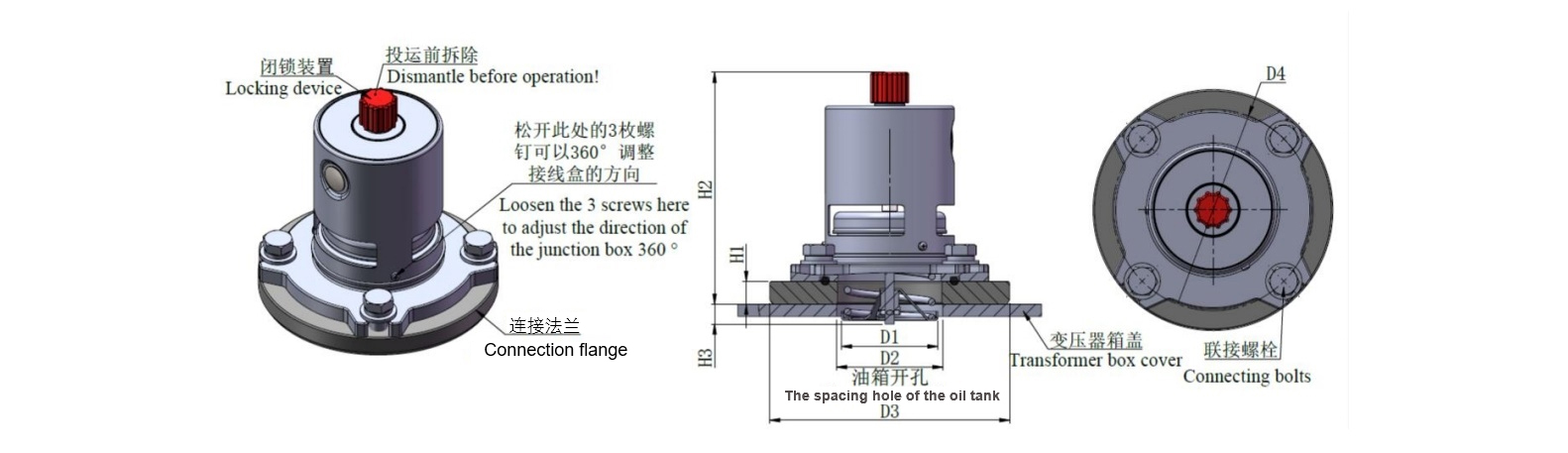
| Product model | Caliber | D1 | D2 | D3 | D4 | H1 | H2 | H3 | Connecting bolts |
| YSF9(/4)-XX/25(S)KJTHB | Φ25 | Φ17.5 | Φ60 | Φ108 | Φ90 | 14 | 140 | 5 | 3-M10×20 |
| YSF9(/4)-XX/50(S)KJTHB | Φ50 | Φ64 | Φ70 | Φ158 | Φ130 | 15 | 162 | 12 | 4-M12×25 |
10. Pressure relief device with bolt connection, electrical signal, vertical outgoing line, and mechanical alarm for sizes of 25K and 50K as shown in the following figure and table.
| Product model | Caliber | D1 | D2 | D3 | D4 | H1 | H2 | H3 | H4 | R | Connecting bolts |
| YSF9(/4)-XX/25(S)KJTHB | Φ25 | Φ17.5 | Φ60 | Φ108 | Φ90 | 14 | 140 | 5 | 95 | 48 | 3-M10×20 |
| YSF9(/4)-XX/50(S)KJTHB | Φ50 | Φ64 | Φ70 | Φ158 | Φ130 | 15 | 162 | 12 | 115 | 60 | 4-M12×25 |
11. Pressure relief device with bolt connection, electrical signal, PG waterproof joint, and mechanical alarm, with a diameter of 25K and 50K as shown in the following figure and table.
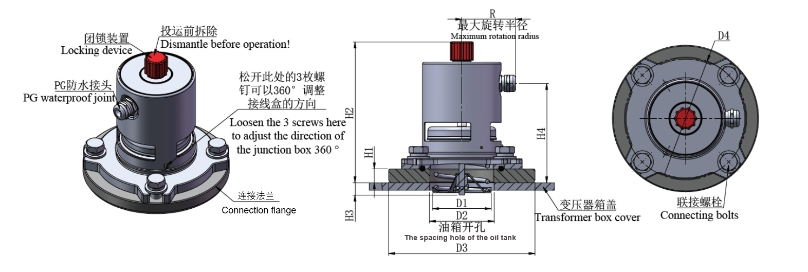
| Product model | Caliber | D1 | D2 | D3 | D4 | H1 | H2 | H3 | H4 | R | Connecting bolts |
| YSF9(/4)-XX/25(S)KJTHB | Φ25 | Φ17.5 | Φ60 | Φ108 | Φ90 | 14 | 140 | 5 | 30 | 85 | 3-M10×20 |
| YSF9(/4)-XX/50(S)KJTHB | Φ50 | Φ64 | Φ70 | Φ158 | Φ130 | 15 | 162 | 12 | 58 | 100 | 4-M12×25 |
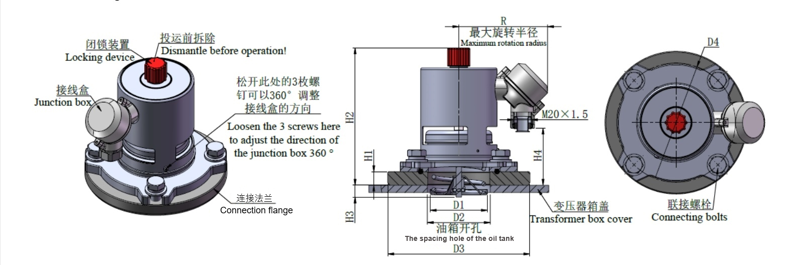
12. Pressure relief device with bolt connection, electrical signal, horizontal outlet, and mechanical alarm for sizes of 25K and 50K as shown in the following figure and table.
| Product model | Caliber | D1 | D2 | D3 | D4 | H1 | H2 | H3 | H4 | R | Connecting bolts |
| YSF9(/4)-XX/25(S)KJTHB | Φ25 | Φ17.5 | Φ60 | Φ108 | Φ90 | 14 | 140 | 5 | 95 | 117 | 3-M10×20 |
| YSF9(/4)-XX/50(S)KJTHB | Φ50 | Φ64 | Φ70 | Φ158 | Φ130 | 15 | 162 | 12 | 115 | 132 | 4-M12×25 |
13. Pressure relief device (bolted connection, with directional injection, and mechanical alarm type) with a diameter of 25DK and 50DK as shown in the following figure and table.
| Product model | Caliber | D1 | D2 | D3 | D4 | D5 | D6 | D7 | H1 | H2 | H3 | H4 | B1 | Connecting bolts |
Number of directional bolts ×specification |
| YSF9(/8)-XX/25D (S)KJTHB |
Φ25 | Φ17.5 | Φ60 | Φ108 | Φ32 | Φ55 | Φ8 | Φ90 | 14 | 140 | 5 | 68 | 57 | 3-M10×20 | 3×M6-30 |
| YSF9(/8)-XX/50D (S)KJTHB |
Φ50 | Φ64 | Φ70 | Φ158 | Φ50 | Φ75 | Φ8 | Φ130 | 15 | 162 | 12 | 85 | 75 | 4-M12×25 | 3×M6-35 |
14. Pressure relief device with bolt connection, directional fuel injection, electrical signal, vertical output, and mechanical alarm for the models of 25DK and 50DK as shown in the following figure and table.
| Product model | Caliber | D1 | D2 | D3 | D4 | D5 | D6 | D7 | H1 | H2 | H3 | H4 | H5 | B1 | R | Connecting bolts |
Number of directional bolts ×specification |
| YSF9(/8)-XX/25D (S)KJTHB |
Φ25 | Φ17.5 | Φ60 | Φ108 | Φ32 | Φ55 | Φ8 | Φ90 | 14 | 140 | 5 | 68 | 30 | 57 | 85 | 3-M10×20 | 3×M6-30 |
| YSF9(/8)-XX/50D (S)KJTHB |
Φ50 | Φ64 | Φ70 | Φ158 | Φ50 | Φ75 | Φ8 | Φ130 | 15 | 162 | 12 | 85 | 58 | 75 | 100 | 4-M12×25 | 3×M6-35 |
15. Pressure relief device with bolt connection, directional fuel injection, electrical signal, PG waterproof joint, and mechanical alarm for sizes of 25DK and 50DK as shown in the following figure and table.
| Product model | Caliber | D1 | D2 | D3 | D4 | D5 | D6 | D7 | H1 | H2 | H3 | H4 | H5 | B1 | R | Connecting bolts |
Number of directional bolts ×specification |
| YSF9(/8)-XX/25D (S)KJTHB |
Φ25 | Φ17.5 | Φ60 | Φ108 | Φ32 | Φ55 | Φ8 | Φ90 | 14 | 140 | 5 | 68 | 95 | 57 | 48 | 3-M10×20 | 3×M6-30 |
| YSF9(/8)-XX/50D (S)KJTHB |
Φ50 | Φ64 | Φ70 | Φ158 | Φ50 | Φ75 | Φ8 | Φ130 | 15 | 162 | 12 | 85 | 115 | 75 | 60 | 4-M12×25 | 3×M6-35 |
16. Pressure relief device with bolt connection, directional fuel injection, electrical signal, horizontal outlet, and mechanical alarm for the models of 25DK and 50DK as shown in the following figure and table.
| Product model | Caliber | D1 | D2 | D3 | D4 | D5 | D6 | D7 | H1 | H2 | H3 | H4 | H5 | B1 | R | Connecting bolts |
Number of directional bolts ×specification |
| YSF9(/8)-XX/25D (S)KJTHB |
Φ25 | Φ17.5 | Φ60 | Φ108 | Φ32 | Φ55 | Φ8 | Φ90 | 14 | 140 | 5 | 68 | 95 | 57 | 117 | 3-M10×20 | 3×M6-30 |
| YSF9(/8)-XX/50D (S)KJTHB |
Φ50 | Φ64 | Φ70 | Φ158 | Φ50 | Φ75 | Φ8 | Φ130 | 15 | 162 | 12 | 85 | 115 | 75 | 132 | 4-M12×25 | 3×M6-35 |
The product provides a variety of color options, specifically described as follows:
| Color card No | Color | Optionality of choice |
| RAL7038 | Agate grey | Default |
| RAL7042 | A Traffic grey A | Optional |
| RAL7035 | Light grey | Optional |

Torque Reference Table
| Number | Assembly position | Thread specification | Recommended torque | Assembly tool specifications | Notes | ||
| 1 | Connecting terminal | M3 | 0.5~1Nm |  |
PH2 | Suggest manual installation |
|
| 2 | Terminal box cover | M4 | 1.5~2Nm | |
PH2 | Suggest manual installation |
|
| 3 |
Flange installation hole |
Ф25 threaded connection | M38×2 | 60±3Nm |  |
||
| Ф25 threaded connection | M48×3 | 70±3Nm | |
||||
| Ф50 threaded connection | M80×3 | 90±3Nm | |
||||
| Ф25 threaded connection | M10 bolt | 18~22Nm |  |
17mm | |||
| Ф50 threaded connection | M12 bolt | 35~40Nm | |
19mm | |||
| 4 | Directional oil inlet | M10 | 6~8Nm | |
10mm | ||
| 5 | Electrical hood | M3 | 0.5~1Nm | |
PH2 | Suggest manual installation |
|


Contact Us
 Tel: 024-23825580
 Email: info@cndeguang.com
 WHATSAPP: +86 15040033053
 Add: Xiangrui Industrial Park, Hunnan New District, Shenyang City, Liaoning Province, China


Integrate closely with upstream R&D, deeply optimize downstream strategic cooperation,continuously lead the domestic market, and pursue innovative development and overseas expansion.
sitemaps


 +86 15040033053
 15040033053/13072495515
 info@cndeguang.com
